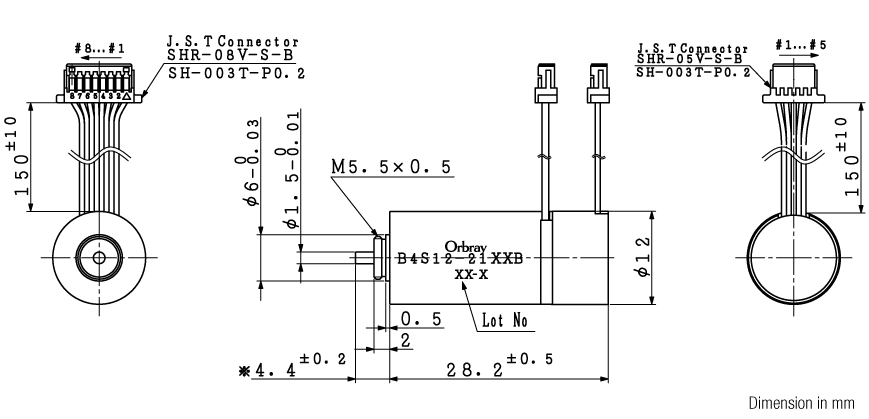
Brushless Motor B4S12-21XX OC/OD/OE
with Hall sensors Brushless Motor.
| Gear | |||
|---|---|---|---|
| SSG12 | SPG12 | - | - |
| Brushless Motor | |
|---|---|
| B4S12-2108B | B4S12-2109B |
| - | - |
| Encoder | |
|---|---|
| ETD12 | - |
| Driver | |
|---|---|
| SHSD24-01A | PSV24-05E |
| - | - |
With Hall
sensors
sensors
Ball
bearing
bearing
Nd-Fe-B
magnet
magnet
Specification
| B4S12-2108B | B4S12-2109B | |
|---|---|---|
| Nomal voltage[V] | 12 | 15 |
| No load speed[rpm] | 15,320 | 19,300 |
| No load current[mA] | 55 | 56 |
| Stall torque[mNm] | 11.09 | 11.64 |
| Stall current[mA] | 1,592 | 1,678 |
| Output power[W] | 4.5 | 5.9 |
| Max efficiency[%] | 66 | 67 |
| Terminal resistance[Ω] | 7.54 | 8.94 |
| Rated torque[mNm] | 1.58 | 1.66 |
| Rated speed[rpm] | 13,132 | 16,543 |
| Rated current[mA] | 275 | 288 |
| Friction torque[mNm] | 0.40 | 0.40 |
| Back-EMF constant[mV/rpm] | 0.756 | 0.751 |
| Torque constant[mNm/A] | 7.22 | 7.17 |
| Slope of N-T curve[rpm/mNm] | 1,381 | 1,659 |
| Mechanical time constant[ms] | 3.49 | 4.20 |
| Rotor inertia[gcm2] | 0.23 | 0.23 |
| Thermal resistance Rth1(coil-housing)[K/W] | TBD | TBD |
| Thermal resistance Rth2(housing-ambient)[K/W] | TBD | TBD |
| Shaft radial play[mm] | 0.05 | |
| Shaft axial play[mm] | 0‐0.1 | |
| Max shaft radial load[N] | 0.5(3.4mm ※1) | |
| Max shaft axial load[N] | 0.15 | |
| Max shaft axial load at standstill[N] | 10 | |
| Operating temperature[℃] | -20‐+80 | |
| Max coil temperature[℃] | 90 | |
| Weight[g] | 18 | |
※1 measured at ( )mm point from flange
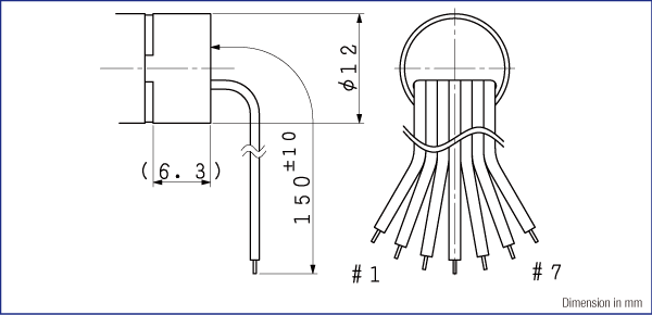
Electrical connections
| B4S12-2108B / B4S12-2109B | ||
|---|---|---|
| #1 | U | Motor winding U |
| #2 | V | Motor winding V |
| #3 | W | Motor winding W |
| #4 | Vdd | Input voltage 3.0V(1.6 - 5.5V) |
| #5 | Gnd | GND |
| #6 | Hu | Hall sensor output U |
| #7 | Hv | Hall sensor output V |
| #8 | Hw | Hall sensor output W |
Specification charts

Encoder ETD12-2C/D/E
2 Channels optical incremental encoder
Specification
| EncoderETD12-2C | EncoderETD12-2D | EncoderETD12-2E | |
|---|---|---|---|
| Sensor | Optical | ||
| Encoder Type | Incremental | ||
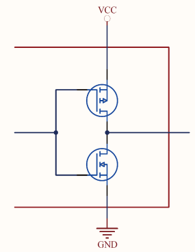
| Output Signal | CMOS/TTL compatible | ||
| Number of Channels[channel] | 2 ※1 | ||
| Resolution (Max. speed = 25,000 rpm)[pulse/rev] | 128 | 256 | 512 |
| Max. Frequency Response[kHz] | 55 | 110 | 220 |
| Supply Voltage, Vcc[V] | 4.5‐5.5 | ||
| Supply Current, typical[mA] | 20 | ||
| Output Voltage “H”[V] | ≧2.4(Max. Vcc) | ||
| Output Voltage “L”[V] | ≦0.4 | ||
| Output current per channel[mA] | 1.5 | ||
| Rise and fall time[ns] | Tr=100, Tf=100 | ||
| Inertia[gmm2] | TBD | ||
| Operating Temperature[℃] | -20‐+85 | ||
| Storage Temperature[℃] | -20‐+85 | ||
※1 For inquiries regarding 3ch specifications, please contact motor sales department.
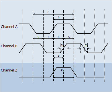
Output signal
(at motor shaft clockwise rotation)

Output signal information
| Cycle C[°e] | 360 |
| Pulse P[°e] | 180 |
| A to B channel phase shift, φ[°e] | 90±45 |
| Logic state width, S[°e] | 90±45 |
*Max error ( ±°e) indicated above.
Electrical connections
| #1 | Motor+ | Motor+※2 |
| #2 | Vcc | DC4.5‐5.5V |
| #3 | Ch.A | TTL compatible |
| #4 | Ch.B | TTL compatible |
| #5 | (Ch.Z) | TTL compatible |
| #6 | GND | |
| #7 | Motor- | Motor-※2 |
| #8 | NC |
※2 When combined with a coreless motor.


