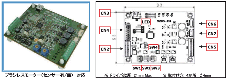
Drivers are used to operate and control Brushless Motor.

SHSD24-01A drive controller applies to all Orbray brushless motors. It works both with/without hall sensor and automatically adjust supply voltage when there is a gap between command and actual rotation speed.
It is equipped with current limit function for protection and status can be checked by LED/LCD and analog voltage output.
OPERATION MODE
| EXT/IO | Rotation speed and direction can be controlled by external input/ output signal. |
| VR | Rotation speed and direction can be controlled by built-in potentionmeter or switch. |
| PC | Rotation speed and direction can be controlled through RS232C from PC (software needed). |
Driver SDSD24-01A Connector
| NAME | FUNCTION |
|---|---|
| CN2 | Power /I/O Connector |
| CN3 | RC232Cconnector |
| CN4 | LCD connector |
| NAME | MATCHING MOTOR |
|---|---|
| CN5(8pin) | With hall sensor (BMN07-BMS16) |
| CN6(4pin) | Sensorless (leadwire) |
| CN7(4pin) | sensorless FPC (BMN04, BMN07) |
[CN2]: Power /I/O Connector
| Pin# | NAME | I/O | FUNCTION |
|---|---|---|---|
| 1 | FG | O | Rotation speed monitor |
| 2 | STATUS | O | Status display |
| 3 | ENABLE | I | Enable input |
| 4 | CW/CCW | I | Switch rotation direction |
| 5 | SPEED | I | Rotation speed setting |
| 6 | +Vcc | - | Voltage input 7.5V∼26.4V |
| 7 | GND | - | GND |
Driver SDSD24-01A SWITCH
| NAME | FUNCTION |
|---|---|
| SW1 | SELECT MOTOR |
| SW2 | SELECT OPERATION MODE / CONTROL |
| SW3 | PI GAIN, SWITCH DIRECTION |
| SW4 | SWITCH OUTPUT VOLTAGE |
Driver SDSD24-01A ELECTRIC SPECIFICATIONS
| ITEM | SPEC VALUE | UNIT |
|---|---|---|
| VOLTAGE (Vcc) | 7.5∼26.4v | V |
| CURRENT CONSUMPTION | 30 | mA |
| OUTPUT VOLTAGE | 3.0∼26.4 | V |
| MAX OUTPUT CURRENT | 2 | A |
| MAX CONTINUOUS CURRENT | 1 | A |
| MAX ROTATION SPEED | 150,000 |
rpm |
INPUT / OUTPUT SIGNAL SPEC (EXT/IOモード)
| NAME | Pin# | STATUS | SPEC VALUE |
|---|---|---|---|
| FG | CN2-1 | 0-5V SIGNAL OUTPUT DUTY 83% / ROTATION | |
| SPEED[rpm]=FG frequency [Hz]×60 | |||
| STATUS | CN2-2 | OPERATION ERROR | 5V |
| OPERATION ERROR | Duty50% Pluse 1.0s | ||
| Standby | 0V | ||
| OPERATING CONDITION | Duty50% Pluse 0.2s | ||
| ENABLE | CN2-3 | ENABLE OPERATION | < 1.00V or GND |
| DISABLE OPERATION | > 4.00V or OPEN | ||
| CW/CCW | CN2-4 | DIRECTION CCW | < 1.00V or GND |
| DIRECTION CW | > 4.00V or OPEN | ||
| SPEED | CN2-5 | SPEED 0rpm | ANALOG VOLTAGE 0V |
| MAX SPEED | ANALOG VOLTAGE 5V | ||
LED turns on in case of setting error.
Specifications are subject to change without notice.


