A motor driver is an electronic device that allows for variable control of a motor's characteristics by amplifying the current according to the input signal. It is important to select the appropriate motor driver based on the type of motor. Orbray offer drivers that are specifically designed to work with our brushless motors.
Additionally, some models are equipped with I/O (Input/Output) ports that enable communication of motor drive status with external devices, and come with dedicated software. By utilizing these features, you can easily drive and monitor Orbray motors, making them highly useful for prototyping and testing.
| products | Applicable Motor | Power supply voltage [V] |
Max output current [A] |
Max rotation speed [rpm] |
Drive method |
|---|---|---|---|---|---|
| SOD12ST | BMN02-05 | 11.5‐12.5 | 0.7 | 180,000 | Sine wave |
| SSD06-R5A | BMN04 series / BMN07 series | 1.8‐5.5 | 0.25 | TBD | PWM |
| SHSD24-01A | Brushless motors (with hall sensor/sensorless) |
7.5‐26.4 | 2 | 150,000 | Speed |
| PSV24-05E | Brushless motors (with encoder/hall sensor)※1 |
6‐26 | 15 | 80,000 | Position, speed, current(torque) |
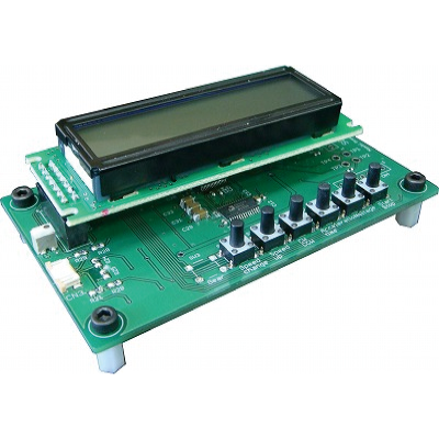
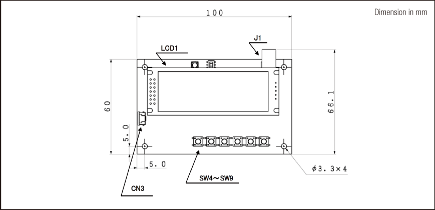
Brushless motor driver
SOD12ST
Specifications
| SOD12ST | |
|---|---|
| Motor type | Brushless motor BMN02-05 |
| Power supply voltage[V] | 11.5‐12.5 |
| Max output current[A] | 0.7 |
| Max continuous current[A] | 0.7 |
| Max rotation speed[rpm] | 180,000 |
| Command method | ‐ |
| Drive method | Sine wave |
| Protection function | ‐ |
| Operating temperature[℃] | 0‐+50 |
| Size[mm] | 66.1×100×32 |
| Weight[g] | 60 |
| Software | ‐ |
| Accessories | AC adapter |
Connectors/switches/pins layout
| SOD12ST | |
|---|---|
| J1 | power input adapter input |
| CN3 | motor connector |
| SW4 | speed setting |
| SW5 | speed count up |
| SW6 | rotation direction change |
| SW7 | motor start-up time setting |
| SW8 | Motor voltage setting |
| SW9 | start/stop |
| LCD1 | setting status and motor operation status display |
| CN3-1 | motor coil W phase |
| CN3-2 | motor coil W phase |
| CN3-3 | N.C |
| CN3-4 | motor coil V phase |
| CN3-5 | motor coil U phase |
| CN3-6 | motor coil U phase |
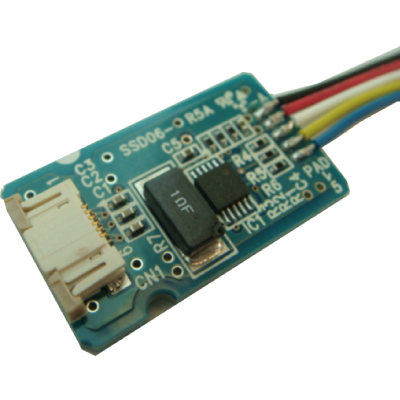
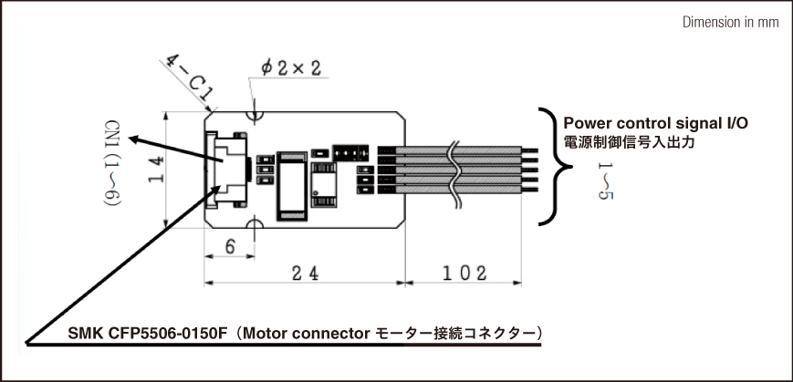
Brushless motor driver SSD06-R5A
Specifications
| SSD06-R5A | |
|---|---|
| Motor type | Brushless motor BMN04 / BMN07 |
| Power supply voltage[V] | 1.8‐5.5 |
| Max output current[A] | 0.25 |
| Max continuous current[A] | TBD |
| Max rotation speed[rpm] | TBD |
| Command method | Speed command PWM input |
| Drive method | PWM |
| Protection function | Current limiting |
| Operating temperature[℃] | -20‐+75 |
| Size[mm] | 14×24×3.8 |
| Weight[g] | 1.1 |
| Software | ‐ |
| Accessories | ‐ |
Connectors/switches/pins layout
| SSD06-R5A | |
|---|---|
| CN1-1 | W phase |
| CN1-2 | W phase |
| CN1-3 | COM |
| CN1-4 | V phase |
| CN1-5 | U phase |
| CN1-6 | U phase |
| Lead wire 1(black) | GND |
| Lead wire 2(red) | VCC |
| Lead wire 3(white) | FG pulse output signal |
| Lead wire 4(yellow) | Rotation direction input signal |
| Lead wire 4(blue) | PWM duty control pulse input |
Brushless motor driver SHSD24-01A
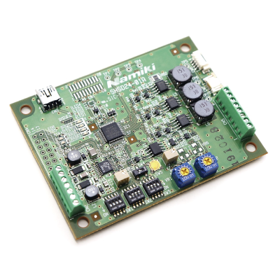
Specifications
| SHSD24-01A | |
|---|---|
| Motor type | Brushless motors(with hall sensor/sensorless) |
| Power supply voltage[V] | 7.5‐26.4 |
| Max output current[A] | 2 |
| Max continuous current[A] | 1 |
| Max rotation speed[rpm] | 150,000 |
| Command method | Digital I/O, analog I/O, serial communication(RS232C・USB) |
| Control method | Speed |
| Protection function | Under voltage protection, excess voltage protection |
| Operating temperature[℃] | -10‐+50 |
| Size[mm] | 83×63×21 |
| Weight[g] | 36.5 |
| Software | SHSD24-01A.Controller |
| Accessories | PCB stat, LCD(option) |
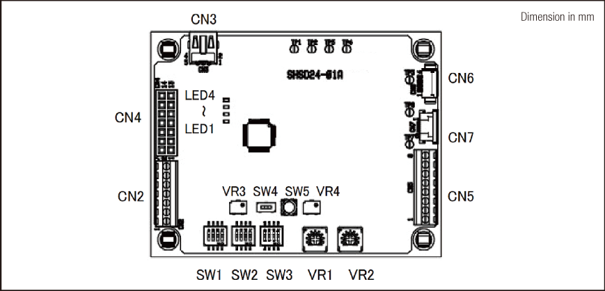
Connectors/switches/pins layout
| SHSD24-01A | |
|---|---|
| CN2 | power supply and each I/O connector |
| CN3 | RS232C communication connector |
| CN4 | LCD connector(optional) |
| CN5 | motor connector(lead wire type) |
| CN7 | motor connector(BMN04,BMS07series) |
| SW1 | model setting SW |
| SW2 | driving mode and control method SW |
| SW3 | PI gain and driving direction SW |
| SW4 | motor voltage SW |
| SW5 | reset SW |
| ※VR1 | adjust PWM duty rate when motor start-up |
| ※VR2 | control target motor speed(In VR mode) |
| ※VR4 | control max output current of motor |
| LED1 | driver setting error display |
| LED2 | motor driving error display |
| LED3 | driver status display |
| LED4 | power status display |
※VR Speed is controlled by a variable resistor mounted on the board.
Brushless motor driver PSV24-05E
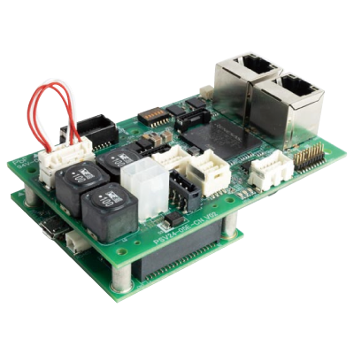
Specifications
| PSV24-05E | |
|---|---|
| Motor type | Brushless motors(with encoder/hall sensor) *Consultation required regarding coreless motor drive |
| Power supply voltage[V] | 6‐26 |
| Max output current[A] | 15 |
| Max continuous current[A] | 4 |
| Max rotation speed[rpm] | 80,000 |
| Command method | Digital I/O, analog I/O, serial communication(RS485・USB), EtherCAT |
| Control method | Position, speed, current(torque) |
| Protection function | Overcurrent, driver overheating, overvoltage, inverter circuit failure, overload, encoder failure, hall sensor failure |
| Operating temperature[℃] | -25‐+45 |
| Size[mm] | 90×58×33 |
| Weight[g] | 84 |
| Software | PSV24-Control |
| Accessories | STO idle connector, power connector, spacer (option), protective cover (option) |
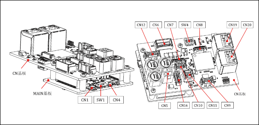
Connectors/switches/pins layout
| PSV24-05E | |
|---|---|
| CN1 | USB |
| CN4 | RS485 |
| CN5 | motor |
| CN6 | digital I/O |
| CN7 | hall sensor |
| CN8 | analog I/O |
| CN9 | absolute encoder |
| CN10 | encoder output |
| CN11 | incremental encoder |
| CN12 | STO |
| CN16 | power input |
| CN19 | EtherCAT(input) |
| CN20 | EtherCAT(output) |
| SW1 | USB/RS485 selection |
| SW4 | ID setting |


Contact
*Click here for detailed inquiries.
*If you cannot find the contact form, please click here.

