Optical attenuators and terminators: How they work and why they are important
Various light transmission and measuring devices are used in optical communications systems. These devices may not work properly or may even be damaged if the light that reaches them is too powerful or if light reflected from the optical fiber enters the devices. Optical attenuators and terminators are used to prevent these issues and ensure accurate data transmission and interpretation.
Table of contents [close]
Optical attenuators and terminators: Why they are used
Optical attenuators are used to adjust the intensity of optical signals. Fiber-optic systems use a wide variety of relays, switches, amplifiers, and other devices that are connected by fiber-optic cables. In some cases, these devices can be several dozen kilometers apart. Because the intensity of the signal diminishes as it travels through the optical fiber, signals that are sent over long distances use very powerful light sources.

However, different optical devices have different limits on the amount of power they are able to handle and process accurately. Some devices can even be damaged if the incoming light is too strong. Therefore, the intensity of the incoming signal must be adjusted to levels appropriate for each device. Optical attenuators are used to reduce the intensity of the incoming light to levels appropriate for the device.
Optical terminators prevent light reflected from open ends of optical cables from travelling back through the cables and interfering with the main signals. The open ends of optical fibers are precisely polished or treated with special agents to reduce the index of refraction when connecting with other cables and devices. When the index of refraction becomes large enough, light will reflect and travel back along the fiber. As this causes interference and reduces the quality of the signal, it must be prevented.
Optical connectors are often used for switching communications paths. Typically, not all of the connections will be used or some incoming fibers will not be connected to the subsequent cable or device during switching. This will leave an end of the optical fiber open to the air. Due the large difference in refractive indexes between the fiber and the air, light is likely to reflect back into the fiber. Optical terminators are connected to the open ends of the optical fibers to prevent this light reflection and thus minimize impacts to the optical communications system as a whole.
Structure of optical attenuators
Broadly, there are two types of optical attenuators. Fixed attenuators provide a constant amount of attenuation. Variable attenuators are able to change the amount of light attenuation.
Fixed attenuators use filters that consist of metallic films inserted diagonally in the fiber to attenuate the light signal. Fibers doped with metal ions that have optical attenuation characteristics can also be used.
In metallic film attenuators, the film absorbs some of the light while also reflecting some of it in oblique directions, thereby reducing the amount of light passing through. In doped fibers, metal ions absorb the light and convert it into heat. Doped fibers are simpler in structure, have excellent power resistance and stability, and are less influenced by light polarization.
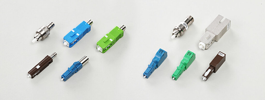
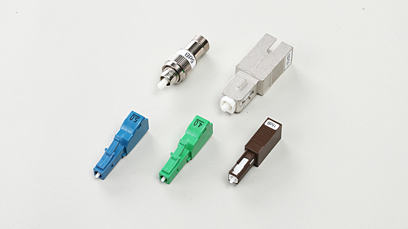
Fixed attenuators come in two types: plug-in types and in-line types. Plug-in attenuators have male-female metal doped ferrules polished to PC or APC profiles. FC, SC, MU, LC, and other connections are available. In-line attenuators have female-female connectors at both ends and are used directly in the communications path.
Variable optical attenuators are used mainly for calibrating optical communications devices and for measuring the characteristics and performance of fiber-optic cables. Variable attenuators can be non-mechanical or mechanical. Non-mechanical variable attenuators use the magneto-optical effect. Mechanical variable attenuators use moveable filters or mirrors to control the amount of light attenuation. For example, variable attenuators that use mirrors are comprised of incoming optical fiber, a collimator lens, a MEMS mirror device that tilts a mirror based on applied voltage, and outgoing optical fiber. When no voltage is applied to the MEMS mirror, incoming light travels through the collimator lens, reflects off of the MEMS mirror, and travels out the outgoing optical fiber. When voltage is applied to the MEMS mirror, it tilts slightly, causing coupling loss, and attenuating the outgoing optical signal.
Principles and structure of optical terminators
The fibers at the end of optical terminators are polished diagonally. This directs any light that is reflected to the side of the fiber and prevents light from travelling back through the fiber core. Optical fibers heavily doped with light-attenuating metal ions can also be used as terminators.
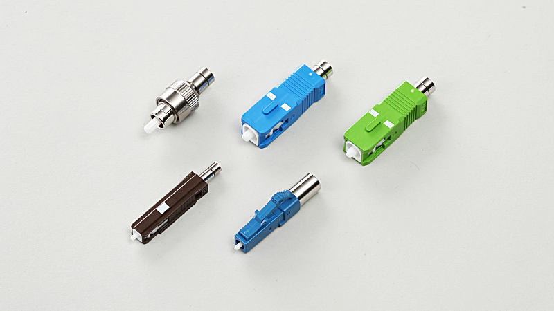
The pigtail cable is a common example of an optical terminator. One end of the terminator is a regular PC-polished connector and connects to the optical fiber as usual. The other end-face of the pigtail is diagonally polished. When light reaches this end-face, it is directed diagonally, preventing it from travelling back down the core. Similarly, connectors with PC-polished ferrules on one end and a diagonally polished ferrule at the other are also used to terminate optical fibers.
Metal-ion doped optical terminators work the same way as metal-ion doped attenuators. Metal ions in the fiber absorb light energy and convert it into heat. This configuration is much simpler than the diagonally polished terminators. Another merit of metal-ion terminators is that energy absorption is spread out along the entire doped range, which prevents localized accumulation of heat. In contrast, when light from a high-power source such as a high-power laser reaches a diagonally polished terminator, energy concentrates on the end-face. The end-face may heat up uncontrollably and cause damage to the fiber and surrounding components. Metal-ion doped optical terminators are available in FC, SC, MU, and LC connector types, and are compatible with PC and APC profiles.
-
Silicon Photonics: Why is it essential for 5G?
-
All About Lasers: How they work, their properties, and their uses
-
What is an Optical Fiber Array? - Connecting devices with optical waveguide elements are indispensable for next-generation high-speed, large-capacity optical communications.

-
Lensed Fibers: Brief introduction to the functions and manufacturing methods

-
Durable non-contact optical connectors: Features and applications of Expanded beam connectors

-
Surface polishing technologies - Essential technologies for semiconductor, MEMS, and LED manufacturing
