Fiber Optic Connector types and applications
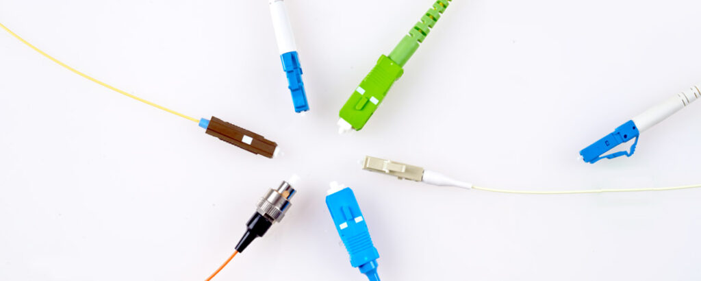
The ends or terminals of fiber optic cables and connectors are important components of optical communications. Today, a wide variety of connectors are available in the market which meet a wide range of precision, cost, and robust requirements.
When selecting a connector, an initial determination must be considered whether the cable is a single-mode (SM) or multi-mode (MM) fiber optic cable.
Compared to multi-mode fibers, single-mode fibers have smaller cores through which light propagates and travels requiring high precision for a connection. Single-mode fiber optics are great for long-distance transmission over dozens of kilometers and are used in carrier networks. On the other hand, multi-mode fibers have larger core areas than the single-mode fibers and require less accuracy in the connections. They are more suitable for indoor applications, such as in data centers, factories, and buildings where transmission distances are much shorter.
Table of contents [close]
- 1. Parameters that determine the quality of connectors: Insertion Loss and Return Loss
- 2. Quality of Connector End Faces
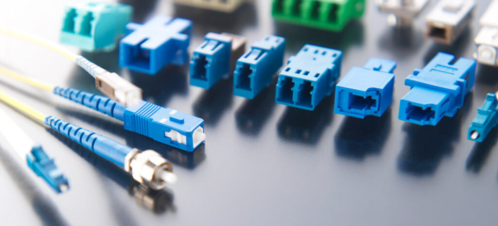
- 3. The structure of fiber optic connectors
- 4. SC connector
- 5. LC connector
- 6. MU connector
- 7. FC connector
Parameters that determine the quality of connectors: Insertion Loss and Return Loss
Connectors are integral parts of any fiber optic transmission line, but they also introduce faults or losses in the transmission path. To minimize the negative effects of such losses, the fibers must be aligned and connected as accurately as possible. Several indicators that denote the optical quality of the connection are used to rate the quality of connectors. In optical communications, these indicators are expressed using logarithmic scales (decibels-dB) because the range of values are very large (on the order of 100 million times) and cannot be expressed as percentages.
One of the main indicators of connection quality is Insertion Loss. This represents the decrease in signal strength when fibers are mated and connected. Of course, a value of zero is desired but a value close to zero is required and the smaller the Insertion Loss value, the better.
Similarly, Return Loss (sometimes referred to as Reflection Loss) is also an important factor, as it is the light that reflects at boundary surfaces, and travels back down the original path. The effect of this light must be minimized or dampened. Unlike Insertion Loss, a large Return Loss or dampening value indicates a high-quality connection, which is desired.
Quality of Connector End Faces
There are three main categories of connectors based on the extent of the finishing of the connector ends or end faces and are regulated by international standards.
Physical Contact (PC) Connector
The end face terminal surface is slightly convex, and the Reflection Loss is 30dB to 40dB.
Ultra-Physical Contact (UPC) Connector
As with PC Connectors, UPC Connectors also have a convex end face terminal surface, but with better processing the Reflection Loss values increase to 40dB to 55dB. UPC Connectors are ideal for digital television broadcasts, carrier networks, data centers, and similar activities that require high reliability.
Angled Physical Contact (APC) Connector
The APC has an end face terminal surface that is similar to PC Connectors, but the end face is angled typically by 8 degrees. This angle prevents the reflected light from recombining and traveling back through the fiber. Reflection Loss increases further to 60dB or better, which is lower than the UPC Connector. APC Connectors are appropriate for applications where high precision optical signals need to be transmitted.
Polishing of connectors
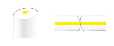
PC (Physical Contact) Polishing
The end face of the ferrule is polished into a convex dome shape. This allows the optical fibers to make closer contact than ferrules that are polished flat. There is no layer of air between the two ends and the amount of reflection is very small. However, some processing artifacts such as scratches do remain, resulting in about 0.3% reflectance at the surface.
Return Loss: 25 dB or more.
Common applications: SC connectors, LC connectors, MU connectors, FC connectors.
UPC (Ultra-Physical Contact) Polishing
This process is similar to PC polishing but adds a chemical mechanical polishing (CMP) step to all but eliminate the most minute scratches, roughness, and other processing artifacts. The reflectance characteristics are significantly improved over PC polishing, with surface reflectance of 0.001% or less. (UPC polishing is currently the standard method for single-mode optical fibers, where reflection can have significant impacts on communications.)
Return Loss: 50 dB or more.
Common applications: SC connectors, LC connectors, MU connectors, FC connectors.
APC (8-degree Angled Physical Contact) Polishing
This process is similar to the above except the whole face is angled by 8 degrees from perpendicular. Any light that reflects off of the fiber surface is deflected by this angle, preventing it from traveling back down the fiber. Reflection characteristics superior to UPC can be attained.
Return Loss: 60 dB or more
Common applications: SC connectors, LC connectors, MU connectors, FC connectors.
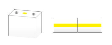
Flat Polishing
The ferrule face is polished flat. This method is commonly used for multi-core ferrules. A layer of air inevitably forms between the two ends of the fiber. Therefore, a refractive index-matching agent needs to be applied to the connecting faces to prevent Fresnel reflection and signal loss.
Return Loss: Depends on each customer’s refractive index-matching agent.
Common applications: MT (mechanically transferable multifiber) connectors
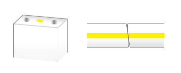
Diagonal Polishing (8-degree Angled)
The face of the ferrule is polished at an angle of 8 degrees from perpendicular, and then further polished using special techniques, resulting in a slightly convex surface. Because the fiber protrudes slightly from the face, it can be used to make physical contact that results in extremely small reflection (attention needs to be paid to the direction of the diagonal polishing to ensure reliable connections can be made).
Return Loss: 55 dB or more
Common applications: MPO (multifiber push-on/pull-out) connectors.
The structure of fiber optic connectors
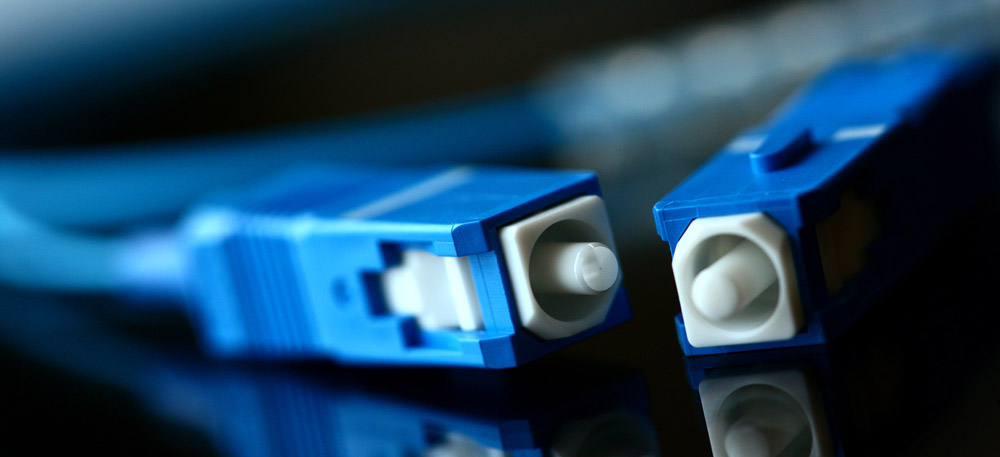
Fiber optic connectors are made of three key components.
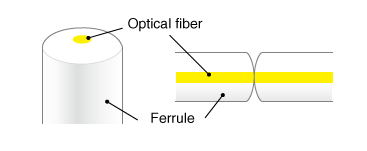
The first component is the ferrule. It aligns the core of the optical fiber with micrometer accuracy, and is usually made of zirconium ceramics, metal, glass, or plastic.
The second component is the connector body. It supports the ferrule and sheaths the fiber or cable. It is commonly made of metal or plastic.
The third component is the coupling mechanism that provides a mechanical connection between the connector body and the optical device. Screws, bayonets, and latches are often used.
There are also simplex and duplex connectors. Simplex connectors have one connector at each end of the fiber optic cable. Duplex connectors have two connectors at each end of a single cable. Various combinations of these elements result in a wide range of connector configurations.
SC connector
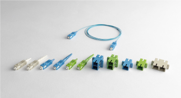
The SC connector was developed in the 1980s. They are characterized by high reliability, durability, and low cost, and have found widespread use. Although connectors before them (ST and FC) were rounded, the SC connector employs a square plastic housing. Fibers are connected with a push-pull mechanism using a 2.5 mm diameter ceramic ferrule. SC connectors are widely used in optical network applications such as cable TV (CATV), inside of optical cabinets, media converters, FTTX (EPON, GPON, etc.).
LC connector
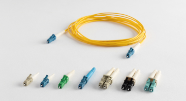
LC connectors use a 1.25 mm diameter ceramic ferrule contained in a plastic housing with a latching mechanism. Some LC connectors have a centering or tuning function that allows the core to be adjusted in various directions after assembly in order to reduce connection losses. With dimensions nearly half of SC connectors, LC connecters are ideal for use in data centers and high-density mounting cabinets. It is commonly used in Fiber To The Home (FTTH) connections, local networks, CATV, data center interconnections (DCIs), etc.
MU connector
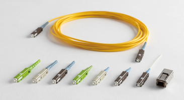
MU connectors are miniature connectors with push-pull mechanisms. It is ideal for both SM and MM type fibers and used in high-density connection applications. It features a plastic housing with a 1.25 mm diameter zirconium ferrule. It is commonly used in data centers, telecommunications, cabling, LAN, etc.
FC connector
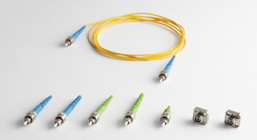
FC connectors have 2.5 mm diameter ceramic ferrules and use metal screw attachment mechanisms. FC connectors are mainly used for SM fibers and are characterized by their stable connection mechanism. They are used in calibration and reference cables for optical devices.
Orbray’s web pages of Fiber optic components are:
-
Introducing Bioceramics: Challenges, features, and applications
-
Lensed Fibers: Brief introduction to the functions and manufacturing methods

-
What are ceramics? From industrial products to wristwatches, the many applications of ceramics

-
MEMS technology: Backbone of smartphone and optical communications technology
-
Silicon Photonics: Why is it essential for 5G?
-
All About Lasers: How they work, their properties, and their uses
