Optical Fiber Current Sensors
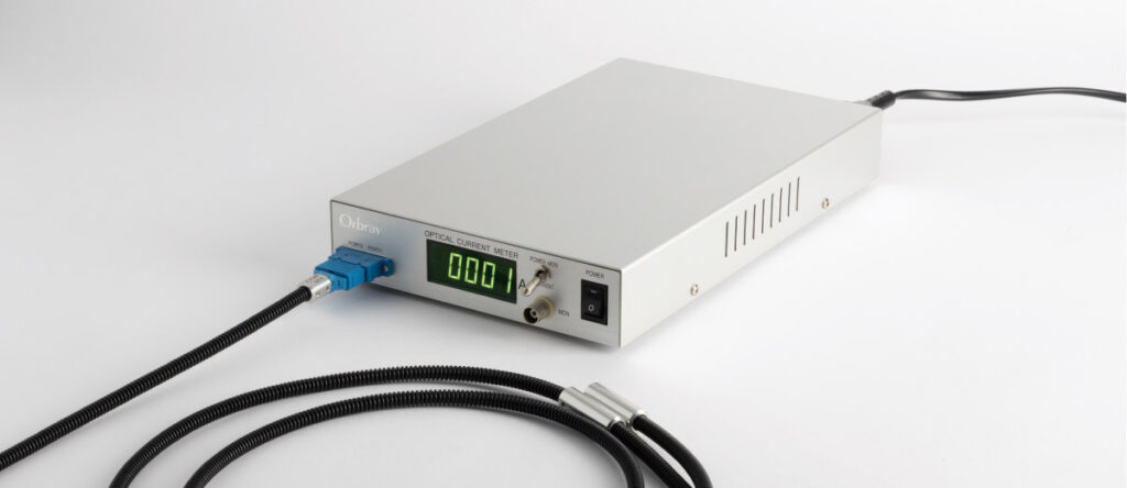
Table of contents [close]
- 1. Introduction
- 2. Principles of Optical Fiber Current Sensors
- 3. Development Examples
- 4. Activities in Japan and Internationally
- 5. Issues and Challenges
- 6. Conclusion
- 7. References:
Introduction
Accurate measurement of electrical current in devices is a fundamental technology that is essential for controlling and monitoring the systems and equipment that many industries and our daily lives depend upon. Typically, current transformers have been used to measure electric current. These consist of an iron core and wire windings, and work based on the electromagnetic induction effect. Shortcomings of this technology include limits to miniaturization, isolation, and other features. There is growing demand for development of current measurement technologies that are not limited by such constraints.
Current sensors that employ the Faraday effect are an example of such technology. First proposed in the 1960s [1], they have been the subject of ongoing research and development for several decades. Initially, bulk-type Faraday sensing elements, such as glass blocks, were used. As fiber optic communications technologies advanced in the 1980s, research began into the use of optical fibers as the Faraday sensing element [2]. Development of practical applications for optical fiber current sensors is progressing due to ongoing research and development, both in Japan and internationally. Orbray has been deeply involved in this development, working closely with multiple other companies and institutions [3], endeavoring specifically to further advance sensor head technologies based on our extensive experience and expertise in optical communications devices.
This paper provides a technical overview of an optical fiber current sensor. First, the fundamental working principles of the sensor, measurement methods, and applications will be explained. Next, the configuration, operation, and characteristics of such a sensor, as well as the unique features and key technological components of a device developed by Orbray, will be examined. In addition, this paper will explore applications for this type of device, including the Orbray device, in Japan and around the world. Finally, future technical considerations will be discussed.
Principles of Optical Fiber Current Sensors
This section describes the Faraday effect and how it is used to detect the electrical current.
The Faraday Effect
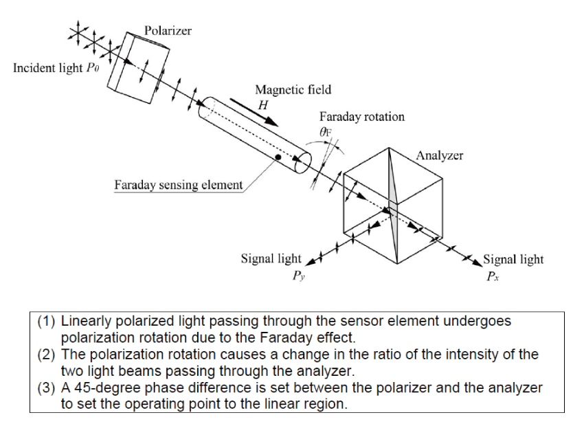
When light passes through a transparent object subjected to a magnetic field, its plane of polarization is rotated. This effect is known as the Faraday effect, and is the basis for optical fiber current sensor technology (Figure-1). The Faraday rotation angle () [rad] is calculated as follows:
θF = VHL (1)
Where:
H: Strength of the magnetic field (component travelling parallel to the light) [A/m]
L: Length of the Faraday sensing element [m]
V: Verdet constant (dependent on the medium and the wavelength of light)
From Equation-(1): The Faraday rotation angle is proportional to the strength of the magnetic field acting on the transparent medium. Therefore, the transparent medium can act as the sensor element if the Faraday rotation angle can be determined. By this method, the magnitude of the current that is the source of the magnetic field can be measured.

Types of Sensing Elements
- Bulk-type element, non-magnetic
Figure-1 shows a bulk-type element being used as the Faraday sensing element. Glass blocks are a typical example of this type of element, and were commonly used in the early stages of research [1].
(2) Bulk-type element, magnetic
Garnet-based crystals used in optical isolators have a large Verdet constant and can be used to produce highly sensitive sensors. However, the following should be considered:
- Ferromagnetic crystals have multi-domain structures, and light is diffracted by the domain walls.
- When applying a magnetic field perpendicular to the direction of light propagation for single magnetic domain formation, effects of magnetic double refraction become significant.
(3) Waveguide element
Optical fibers have been used successfully as waveguide-type Faraday sensing elements, as will be outlined later in this paper. When a magnetic field is applied to a single-mode optical fiber, light polarization propagating in the fiber rotates in response to the applied magnetic field. Therefore, the fiber can be used as a Faraday sensing element.
Types of Sensing Methods for Optical Fiber Current Sensors
The intensity modulation method and the interferometric method are two methods to convert the Faraday rotation angle into electrical signals, completing the process for obtaining an output signal proportional to the current being applied. These methods are described below.
Intensity Modulation Method
In the configuration shown in Figure-2, the analyzer (polarizing prism) is offset 45 degrees to the polarizer. Faraday rotation increases with the strength of the magnetic field, impacting the intensity of light (Px, Py) transmitted through the analyzer. Therefore, the light intensity can be converted into an electric signal corresponding to the Faraday rotation occurring in the Faraday sensing element.
This type of device is relatively simple to manufacture. However, accuracy of DC measurements is low.
Interferometric Method
The interferometric method utilizes the loop-type interferometer used in optical fiber gyros [4]. Many different configurations have been proposed. Figure-3 shows one example of a configuration and will be used to describe the method in detail.

Light emitted from a source passes through an optical coupler and then a polarizer. The polarized light then travels through a polarization-maintaining type of optical fiber whose polarization angle is tilted 45 degrees with respect to the polarizer, propagating light in two polarization modes: the slow axis and the fast axis. These modes are converted into circularly polarized light by a quarter-wave plate, and the light is propagated through the sensor fiber. A mirror at the end of the sensor fiber returns the light. When this happens, the polarization modes are exchanged (right-handed polarized light → left-handed polarized light, and vice versa). During this round trip through the sensor fiber, the magnetic field produced by the current induces the Faraday effect on the light. This produces a phase difference between the two polarization modes that is proportional to the current. The returning light passes through the quarter-wave plate again and is converted into linearly polarized light orthogonal to the incident light. The component of light that was propagated on the slow axis when entering the transmission fiber propagates on the fast axis on the return path, and vice versa. The two polarization modes interfere with each other at the end of the fiber, enter the polarizer, become converted to light intensity according to the change in polarization, pass through an optical coupler, and are converted into an electrical signal by a photo detector (photo diode).
The signal is processed in combination with a phase modulator to ensure linearity and stability of the output. Methods such as passing the output of the photo detector through a bandpass filter with central angular frequency of ωm and 2ωm and comparing the levels of the two (phase-sensitive detection) are used.
In this interferometric method, by inserting a phase modulator in the optical path, the change in incident light intensity and the phase change due to the Faraday effect are differentiated and corrected for.
Development Examples
Here, an intensity modulation sensor developed by Orbray is described as an example of ongoing developments in the field [3].
Configuration and Operation
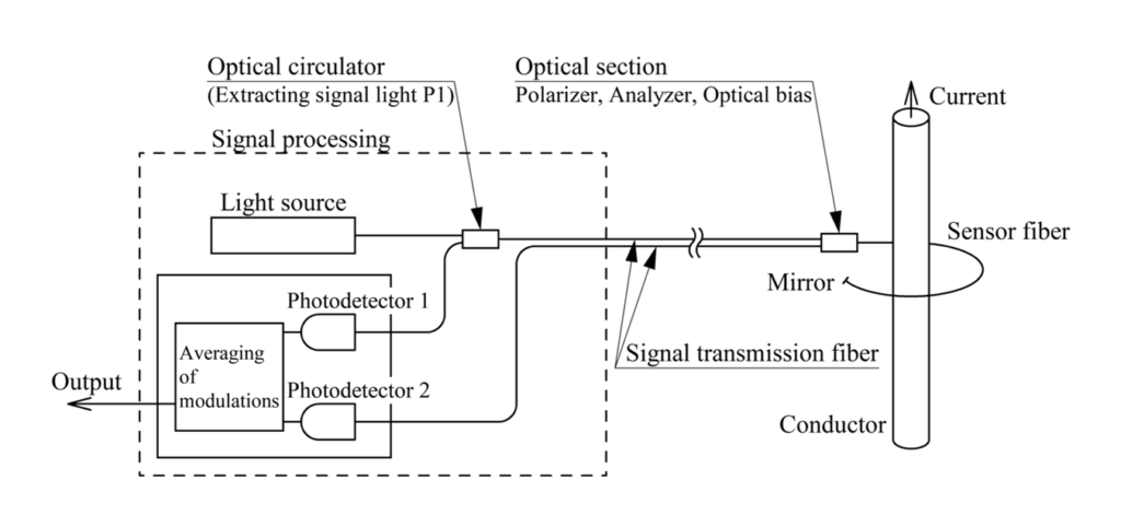
Figure-4 shows the configuration of the sensor. Light is produced by a 1550 nm broadband source. It travels through a single-mode transmission fiber to the polarizer/ analyzer /optical bias section (the “optical section”). The light is linearly polarized by the polarizer and propagates through the sensor fiber. When it reaches the mirror at the end of the fiber, it returns to the optical section. The polarization angle is tilted 45 degrees by the optical biasing element and separated into two orthogonal linear polarizations. When light propagates through the sensor fiber, the plane of polarization is rotated by the Faraday effect of the current-induced magnetic field, and the intensity of the two beams varies according to the angle of rotation. The photo detector converts the intensities of the two angles into electrical signals proportional to their intensities. By averaging the degree of modulation of these electrical signals, a voltage output proportional to the current can be obtained.
Foundational Technologies
This section describes the fundamental technologies used to achieve a stable, low-cost sensor with simple construction.
Low Birefringent Sensor Fiber
Conventional single-mode optical fibers show large photoelasticity effects. This makes it difficult to distinguish whether the changes in polarization are due to photoelasticity or the Faraday effect. This issue was solved by using sensor fibers composed of flint glass, which have low photoelasticity coefficients [5].
A method of twisting optical fibers is known as a way to suppress the effects of photoelasticity in silica-based single-mode fibers. Spun optical fiber and other methods are being used by other organizations.
Reflective Optical Systems
Another issue with polarized light is that the degree of polarization depends on the shape of the fiber’s curve. In order to eliminate the effects of fiber curvature, mirrors are placed at the end of the fiber to reflect the light back through the fiber.
Signal Processing
To compensate for measurement errors caused by changes in factors such as the intensity of the light source, signal loss in optical components, and optical bias due to temperature changes, a newly devised signal processing method called “averaging of modulations” is used.
Compact and Stable Optical Device
The sensor head must be compact and maintain high accuracy despite changes in temperature. To achieve a compact design, a polarizer that doubles as an analyzer and magnetic garnet with a rotation angle of 22.5 degrees (45 degrees of optical bias in both directions) were used.
In addition, although the Verdet constant of the sensor fiber has a temperature dependence of 0.01%/K, the temperature dependence of the sensor head as a whole is improved by utilizing the temperature dependence of the rotation angle of the above-mentioned magnetic garnet.
Characteristics
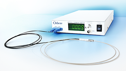
Figure-5 shows a model of Orbray’s device. Its specifications are outlined in Table-1.
| Item | Specification |
| Rating current | 5,000 Arms |
| Frequency range | 3 to 10 kHz (-3 dB) |
| Operating temperature (at the sensor head) | -20 to 80°C |
| Accuracy | Within ±0.5% |
| Sensor fiber length | Less than 5 m |
| Transmission fiber length | 10 km |
Features
Some prominent features of the optical current sensor are as follows:
- Optical fiber allows for electromagnetic isolation, the absence of an iron core, and a compact design.
- Easy installation: The flexible optical fiber is wrapped around the conductor for accurate measurement. (Output is proportional to the current, independent of the fiber curvature or the position of the conductor.)
- The sensor head is less susceptible to electromagnetic noise, and facilitates long-distance signal transmission.
- There is no distortion of output from magnetic saturation. Large currents can be measured accurately, such as during power system malfunctions.
- The sensor enables a faster response, and the electromagnetic effect of mounting the sensor to the circuit to be measured is almost negligible.
Applications
Several applications focusing on the features outlined in Section 3.4[Features] are described below.
Fault Section/Point Identification System in a Power Facility
(1) Underground powerline failure identification system
To address malfunctions that occur in a power system that includes underground power transmission lines, a “failure section identification system” to determine whether the failure occurred within the range of the underground transmission line [6] has been developed. Sensors that are attached to both ends of the cable detect the three-phase current (zero-phase current) at the time of the incident, and determine the section of the system where the failure occurred. The equipment has been put to practical use in 66kV underground transmission lines in Japan. A device for air-insulated substation equipment based on a similar algorithm has also been developed and put to practical use [7].
(2)Surge current-based failure point identification device
Failure point locators have been developed to determine failure points in underground transmission lines [6]. These devices are attached to both ends of each phase of a power cable. When a failure occurs, both sensors detect the surge current arriving from the failure point. The failure point is determined from the difference in the arrival times of the surge current. The equipment has been put to practical use in 275kV underground transmission lines in Japan.
Current Analyzers for Power Electronic Devices
(1)Analysis of power semiconductors (broadband applicability)
Broadband current measurement is required to evaluate the performance of inverters and other power electronic devices. The substrate to be measured is narrow, and the electromagnetic noise is high. There is also demand for minimizing the interference that occurs from measurement of the target current. Due to the features described in Section 3.4[Features], the Orbray sensor is ideal for such applications. For example, its application in testing automotive inverters has been reported [8].
(2)High-order harmonic analysis in substations
When installing power electronic equipment in substations, the presence or absence of harmonics and their influences should be evaluated. The Orbray device was used for the continuous analysis of high-order harmonics up to 9 kHz at a selected site [9].
Protective Relays
Protective relay systems detect the occurrence and mode of failures in power equipment, and operate switches to prevent the failures from spreading. The sensor that has been developed by Orbray is ideal for use in protective relays due to its features. Effective results were reported from tests of a sensor of this type that was assembled for a protective relay [10].
Activities in Japan and Internationally
This section describes trends in the development of optical fiber current sensors at Japanese and overseas institutions.
Direct Current Measurement
Development of devices for measuring direct current is being carried out at institutions in Japan and abroad. Direct current should be measured by the interferometric method, because a mechanism that compensates for slight changes of characteristics over time and the effects of temperature changes is needed. Exemplary applications of this technology are introduced below.
(1)Application for DC devices
A Japanese case is described in references [11] and [12]. In this case, the device was used in the configuration of a protection relay system for a submarine DC cable system. Another Japanese case is reported in reference [13]. In this case, the device was used in a protection relay for a DC substation of an electric railway; field tests were conducted at a railway substation.
(2)Application at a chemical plant
References [14] and [15] describe an overseas case. In this example, a device for measuring a DC current of several hundred kA in aluminum refining facilities was developed, put to practical use, and commercialized.
Regarding Standards
IEC Standards Regarding Digital Interfaces
Modern substations are digitalized and are ideal for the application of this new generation of sensors (such as the Rogowski coil current sensors, fiber optic current sensors, fiber optic voltage sensors, etc.). The establishment of IEC standard IEC61869 for interfaces in digital substations is currently underway. Information regarding the enactment of IEC61869 is quite voluminous and complex. Reference [16] has organized much of this information and is a useful reference.
OITDA Standards
Methods for operating and evaluating optical fiber current sensors are different from those for conventional current sensors in many ways.
In 2017, the Optoelectronics Industry and Technology Development Association (OITDA) established standards for evaluating the features of optical fiber current sensors [17] and published them on its website to promote the proper handling and dissemination of the technology. In 2020, the IEC established an international standard based on the existing OITDA standard [18]. Furthermore, the OITDA standard for characterization of optical fiber voltage sensors was published in 2022 [19] with the same motivation. Work is currently underway to establish IEC standards for optical fiber voltage sensors based on this OITDA standard.
Issues and Challenges
Technical challenges for our devices that were noted in Section 3[Development Examples] are described in this section.
Measurement of Direct Current
As described in Section 4.1 [Direct Current Measurement], interferometric sensors are required to measure direct current. As the market for renewable energy such as solar and wind power grows, the demand for effective DC sensors is expected to also increase. However, as seen in Section 2.3.1[Intensity Modulation Method] and Section 3[Development Examples], optical fiber current sensors are not applicable to direct current measurement. Orbray is working to develop practical DC sensors with simple configurations by using proven fundamental technologies such as low refraction sensor fibers.
Broadband and Small Current Sensors
One field that is becoming difficult to handle with existing technologies is power semiconductor applications, as mentioned in Section 3.5.2[Current Analyzers for Power Electronic Devices]. Fiber optic current sensors can be effective in this field due to their broad bandwidth, flexibility, and low impact on the circuit. However, they lack the sensitivity to measure currents of just a few amperes. Improving low current sensitivity by increasing the Verdet constant of the sensor fiber, and improving the signal-to-noise ratio are challenges that need to be addressed. The bandwidth is a function of the signal processing circuit and the propagation time of the light in the sensor fiber. For example, when attempting to measure a current with a frequency of 100MHz, the sensor fiber length must be 20 cm or less.
Lead-Free Devices
Low photoelasticity in the sensor fiber is accomplished by using glass containing lead oxide. Universities in Japan are conducting research on lead-free low photoelasticity glass [20] [21] [22]. Applications are expected for sensor optical fibers as well as other optical elements that handle polarized light, such as prisms and lenses.
Conclusion
Along with the advancement of optical communications technology, many decades of research and development that began in the 1960s have led to the advancement of practical applications of optical fiber current sensors in recent years. Optical fiber current sensors find uses in a wide range of fields because they can stably measure current by the simple wrapping of a flexible optical fiber around a conductor.
In addition to commercializing the sensing device we have produced, Orbray continues to improve it, and is working to discover new fields of application.
Finally, this paper concludes by mentioning the great achievements of Mr. Yoshihiro Konno and the contributions he has made to this work.
References:
[1] S. Saito, et al.: IEEE J. Quantum Electronics, Vol.QE-3, No. 11, p.589, 1967
[2] A. Rapp and H. Harms: Applied Optics, Vol.19, No.22, p.3729, 1980
[3] K. Kurosawa, T. Yamaguchi, M. Sasaki, The Review of Laser Engineering, Vol.45, No.1, 2017
[4] J. Blake et al.: IEEE Trans. on Power Delivery, Vol.11, No.1, p.116, 1996
[5] K. Kurosawa and I. Masuda: Proc. 9th Opt. Fiber Sensors Conf., p.415, 1986
[6] S. Nasukawa, et al.: Proc. 7th JICABLE Conf., Session A.5, No. A5.5, 2007
[7] E. Itakura et al.: Takaoka Review, Vol.50, No.1, p.10, 2005
[8] K. Torii, et al.: Proc. FISITA-2008, No. F2008-06-050, Germany, 2008
[9] T. Miyazawa: On-site Electrical Technologies, Vol.46, No.54, p.29, 2006 (title translated)
[10] T. Yamaguchi, et al.: Takaoka Toko Review, Vol.1, No.1, p.44, 2014
[11] M. Takahashi, et al.: Magnetics Japan, Vol.1, No.3, p.118, 2006
[12] Y. Hirata, et al.: 2012 IEEE/PES, T&D Conf., DOI:10.1109/TDC. 2012. 6281570
[13] H. Hayashiya, et al.: IEEJ Transactions on Electronics, Information and Systems C, Vol.126, No.6, p.736, 2006
[14] K. Bohnert and P. Guggenbach: ABB Review Vol.1, p.7, 2005
[15] M. Wiestner, et al.: Aluminium 2005-1-2
[16] IEEJ Technical Report No.1475, 2020.3, ISSN 0919-9195 (title translated)
[17] OITDA Standard: Fiber optic sensors–Polarimetric current measurement, OITDA FS 01, 2017
[18] IEC Standard: Electric Current Measurement–Polarimetric Method, IEC61757-4-3, 2020
[19] OITDA Standard: Fiber optic sensors–Voltage measurement–Polarimetric method, OITDA FS 02, 2022
[20] H. In, H. Takebe, K. Morinaga: Journal of the Ceramic Society of Japan, Vol. 111, No. 1294, p.426, 2003
[21] A. Saitoh, et al.: Japanese Journal of Applied Physics, 57, 2018
[22] K. Hayashi, et al.: Optical Materials, Volume 96, October 2019

-
Lensed Fibers: Brief introduction to the functions and manufacturing methods
-
All About Lasers: How they work, their properties, and their uses

-
Pioneering the Future of Multi-Core Optical Fiber Connections : Orbray's Optical Fiber Bundling and Light-Induced Self-Written Optical Waveguide Technology

-
What is a Ferrule? : The history and development of the ferrule continues today with its ever pursuit of high accuracy of 1um or less at reduced costs

-
What are optical interconnects and fiber optics?
-
Silicon Photonics: Why is it essential for 5G?