Reduction gears: Types and features
Reduction gears, also known as speed reducers, are used in many products that are powered by motors, such as industrial robots and machine tools. In modern industrial fields, reducers are essential components for high-precision processing and precision control.
This article describes different types of reduction gears, their mechanisms, benefits, and distinguishing features of each.
Table of contents [close]
What are reduction gears?
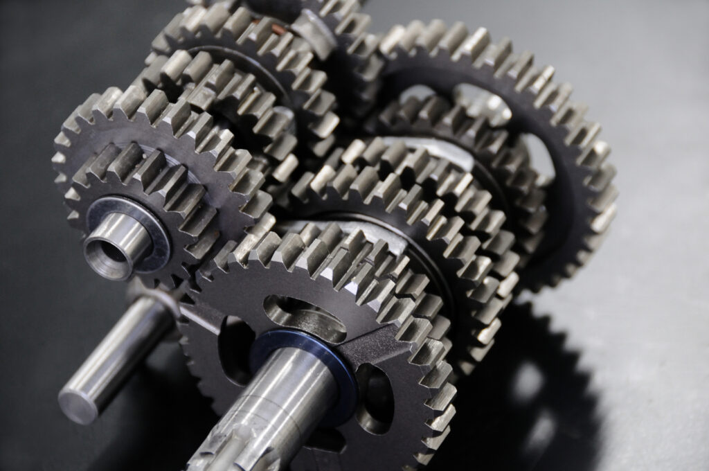
The mechanisms, applications, and necessity of reducers is explained below. Gaining a deeper understanding of reducers and how they are used is essential for selecting the right one for your needs.
Mechanics of reduction gears
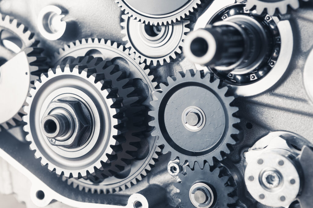
A reduction gear is an arrangement of gears that reduces the number of rotations of a power source such as a motor. The arrangement also has the effect of increasing the amount of torque. This makes it possible to set the most appropriate rotational speed and torque for the application.
The simplest reduction gear arrangement is a combination of two gears: one on the input side and the other on the output side. The ratio of the number of teeth on each gear is called the reduction ratio.
For example, if the output gear has 100 teeth and the input gear has 50 teeth, the reduction ratio is 2:1. In this case, the number of rotations of the output gear will be 1/2 that of the input gear and the torque at the output gear will be nearly twice that of the input gear. (More precisely, the output torque is the input torque multiplied by the reduction ratio and the torque transmission efficiency of the gear).
In many situations where speed reduction is required, simple, two-gear combinations may be insufficient. For example, to achieve a high reduction ratio with just two gears, the input gear must be very small (fewer teeth) and the output gear very large (more teeth). There are physical limitations on the ratio that can be achieved with just two gears.
A solution is to add more gears to the combination so that the output gear becomes the input gear for the next gear in the reducer. These are called gear stages. One set of gears makes up one stage, two sets make two stages, and so on.
High gear ratios can be achieved by using a larger number of gears. However, torque transmission decreases as gears are added. Backlash on the output shaft also tends to increase.
For applications that require precision, the reducer should be made of precision-machined gears and reducers. Architectures that reduce backlash should be selected.
In addition, most reducers use lubricants such as grease to help it run smoothly, helping to reduce noise and significantly extend service life. The lubricant used should be selected based on the environment and mechanical conditions of the reducer, such as load and speed.
Why are reduction gear needed?
Most motors have a fixed range of rotational speed and torque that is most efficient for their operation. However, work that needs to be done generally requires much lower speeds and higher torque than what the motor can deliver efficiently.
In other words, the motor has high speed and low torque, while the work requires low speed and high torque. Attempting to complete the work with just a motor will require operation outside of the efficiency zone, leading to excessive heat generation, shorter lifespan, and other negative effects unless a larger, more costly motor is used.
In such cases, a reduction gear can be used to reduce the speed and increase the torque of the motor output. The appropriate gear ratios can be selected to achieve the required speed and torque at the output gear while the motor operates in its most efficient range.
Reduction gears are used in many applications
Reduction gears are used when precise control of the operation is required. They can be found all around us in many applications. Here are some major examples:
・Mobility equipment such as elevators and escalators
・Factory equipment such as conveyor belts and industrial robots
・Automatic equipment such as automatic doors and shutters
・Precision equipment such as medical, surveying, and optical equipment
From everyday equipment such as automatic doors and elevators to robots working deep inside a factory, reducers are used in a wide range of applications. Reduction gears are essential components for equipment that uses motors as a power source.
Benefits of using reduction gears

This section briefly breaks down the benefits that can be obtained by using reduction gears.
High torque, small size
The most obvious way to increase torque is to use a bigger motor. However, in many cases, space for motor installation is limited, especially if the motor is installed inside machines, robots, or other equipment. Torque can also be increased by increasing the electrical power input. But if more electricity is used, the motor will generate excessive heat, leading to decreased efficiency and eventual failure.
Reduction gears can be used to generate several hundred times the torque from the same motor. This means more torque can be obtained from the same size motor, or a smaller motor can be used to maintain the current torque requirements. In addition, the appropriate amount of electric power can be used so excessive motor heat can be avoided and the motor can run safely and efficiently.
The types of reduction gears and features of each
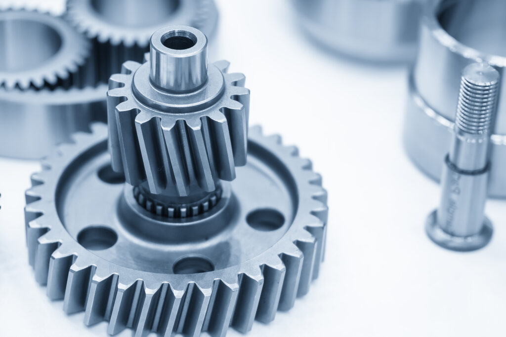
This section describes different types of reduction gears and specific features of each. A good understanding of the types and features of reduction gears is essential for selecting the right one for your application.
Parallel shaft reduction gears
Parallel shaft reduction gears combine several stages of spur gears (which have excellent power transmission) and helical gears (which operate quietly) to reduce rotational speed. One notable feature is that the input and output shafts are parallel to each other.
A wide range of gear reduction ratios can be set by combining gears in several stages, making this type of reducer useful in a variety of applications.
Worm gear reduction gear
Worm gear reduction gears combine a worm gear, which is a threaded gear, with a worm wheel, which is a helical gear. The worm gear acts as the input axis and the worm wheel acts as the output.
Move separately. The input gear rotates perpendicular to the output gear and allow worm gears to achieve high reduction ratios in a single stage.
Energy is transmitted from the worm gear to the worm wheel through a sliding motion, which can tend to generate heat, and the duty factor is generally set very low. On the other hand, worm gears tend to be much quieter than planetary gears.
Bevel gear reduction gear
Bevel gear reduction gears use a type of bevel gear known as a hypoid gear to reduce the input speed. The axis of the output is rotated 90 degrees in relation to the input.
Bevel gears have strong teeth, so they perform well even under heavy loads and exhibit high durability. In addition, they feature high duty factors and are less likely to retain heat than worm reduction gears.
Planetary gear reduction gear
Planetary gear reduction gears have a sun gear in the middle and multiple planetary gears inside a ring gear. There are fixed and movable internal gears. Using gears with different numbers of teeth allows these reducers to produce high gear ratios and large reductions in speed.
Strain wave gear reduction gear
Strain wave gear reduction gears are high-performance reduction gears that use the strain wave gearing principle. They are driven by an elliptical wave generator that is placed inside a thin, cup-shaped elastic metal body. When the wave generator rotates and creates waves in the elastic metal body, the body comes into contact with the external circular gear. As the teeth of the elastic metal body engage the teeth of the external circular gear, the body rotates.
In addition to high torque, low inertia, and compact size, strain wave gear reduction gears have almost no backlash, and have low vibration and noise, allowing for quiet and stable operation.
Orbray’s geared motors
This section describes the two different types of geared motors that Orbray offers, each with a unique set of useful features.
What are geared motors?
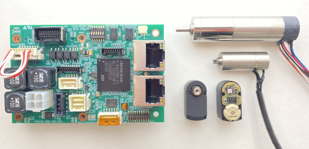
A geared motor is a product that incorporates a reduction gear onto the output shaft of a motor. Geared motors are highly versatile as they exhibit low rotational speeds and high torque compared to the motor alone. They can be used in transport equipment and as driving components in machinery, among other applications.
Gear type
The two types of gear heads used in Orbray’s geared motors are spur gear heads and planetary gear heads.
Spur gear heads are commonly found in many applications and use cylindrical gears with teeth cut parallel to the axis of rotation. They have relatively simple structures, with a small number of parts and gear engagement points. They operate quietly with no thrust load. The direction of rotation of the input and output gears differs depending on the number of stages.
Planetary gear heads are characterized by the fact that the input and output shafts can be arranged coaxially. A large number of gears are engaged allowing for high torque transmission, and high reduction ratios can be achieved with a small number of stages. They are called planetary gears because of their structure in which planetary gears rotate around a central gear (the sun gear).
Summary of reduction gears
Reduction gears are devices used to improve the operating efficiency and safety of many machines and devices, such as industrial robots and machines tools. They play an important role in sectors where high-precision processing and control are essential.
As the industrial manufacturing field continues to evolve, the demand for precision performance and reduction gears is expected to grow even more in the near future.
Click here to find out more about Orbray’s reduction gears:

