Improving Ceramic Injection Molding Quality: Using Simulation to Uncover "Invisible Causes"

Table of contents [close]
- 1. Introduction to how Orbray leverages computer analysis
- 2. What is CAE? How computers are transforming manufacturing
- 3. Challenge of injection molding ceramics: Cracks that appear after sintering
- 4. Why do cracks form? The invisible impact of non-uniformity
- 5. Making the invisible visible with fluid analysis
- 6. Finding “optimal conditions” automatically with parameter optimization
- 7. Verifying the results through experimentation: Complete elimination of cracks
- 8. Improving development processes: A new workflow for engineers
- 9. The future of manufacturing with CAE
- 10. Conclusion
Introduction to how Orbray leverages computer analysis
Orbray’s Mr.Goki Nishimura, of the Technology Division, presented at a webinar hosted by Cybernet Systems Co., Ltd., entitled “Revolutionizing the Development Process: Design Optimization with Injection Molding Simulation,” on November 13, 2025.
Based on the contents shared during the seminar, this article examines common quality-control issues faced in ceramic injection molding and demonstrates how computer-aided engineering (CAE) can be utilized to resolve them.
What is CAE? How computers are transforming manufacturing
CAE (computer-aided engineering) is a technology that uses computer simulations to predict and verify product performance and manufacturing processes prior to physical production.
Traditional manufacturing often relies on a trial-and-error approach, iterating between building a prototype, testing it, identifying issues, redesigning, and then building the prototype again. This method is inherently time-consuming and costly.
CAE enables engineers to test dozens, or even hundreds, of conditions virtually before a single physical prototype is manufactured. It functions as a “digital laboratory,” allowing teams to explore various possibilities and scenarios in advance.
Today, CAE is an essential part of the workflow across a wide range of industries, from automotive crash safety testing and aircraft aerodynamics to earthquake-resistant structural design. Even everyday items, such as smartphones and home appliances, undergo rigorous optimization with CAE before reaching the market.
Challenge of injection molding ceramics: Cracks that appear after sintering
Orbray manufactures its core products, precision jewel components and optical communication parts, using ceramic injection molding.
Ceramics are closely related to pottery. They are light, resistant to wear, and can tolerate very high temperatures. These are desirable properties for a wide range of products.
However, these characteristics also make them extremely difficult to machine using traditional methods. To address this, a ceramic powder is mixed with a resin binder. This mixture is injected into a mold to create the component's initial shape. This is then heated to very high temperatures to burn off the resin and fuse the ceramic particles together, in a process called sintering.
Sintering ceramics is similar to that of pottery. Ceramics are sintered at temperatures exceeding 1,000℃, transforming the molded powder into a dense, durable product. However, this process presents a critical issue: the components are prone to cracking after sintering.
Ceramic Injection Molding: Methods and Challenges
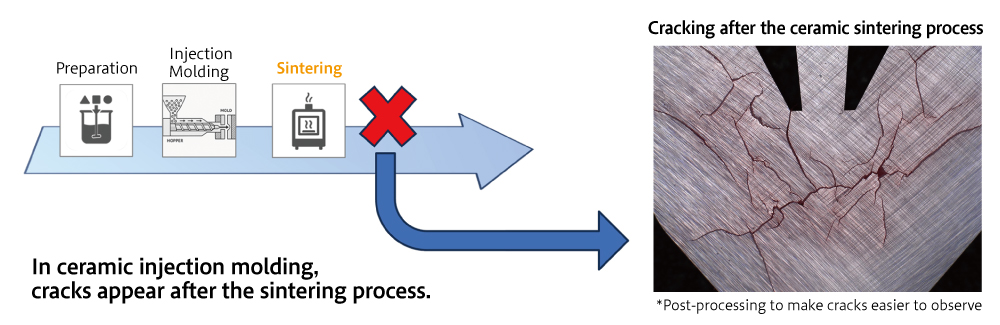
How can cracking be suppressed?
Reduce non-uniformities in the injection process
Need to visualize uniformity ⇒ Introduction of CAE
Non-uniformity can occur through:
- Pressure distribution
- Temperature distribution
- Internal stress
- Strain
- Material distribution
- Flow balance
It is difficult to measure and visualize.
Why do cracks form? The invisible impact of non-uniformity
Orbray focused on “non-uniformity” of the binder mixture as a possible cause of the cracks.
In injection molding, dissolved materials are injected into a mold. Throughout this process, critical factors such as
・flow rate,
・cooling speed,
・and internal pressures
vary significantly across different areas of the mold. For instance, the temperature and pressure at the injection point differ vastly from those at the end of the flow path.
We hypothesized that these local non-uniformities lead to different rates of shrinkage during the sintering process, ultimately resulting in cracks. However, verifying this hypothesis through direct measurements is extremely difficult.
It is impossible to visually see what is happening inside the mold during injections. At the same time, the high-temperature, high-pressure conditions of injection molding make it extremely challenging to install sensors for real-time data collection. To overcome these physical limitations, we introduced CAE to “make the invisible visible,” by simulating the internal behavior of the material that could not be observed directly.
Making the invisible visible with fluid analysis
To address the issue, Orbray first turned to fluid analysis.
Fluid analysis is a technology used to simulate the behavior of liquids and gases using computational models. The same principles are used for weather forecasting, aerodynamic design for aircraft, and river flow predictions.
In manufacturing, specifically, simulating how materials like resin or ceramics fill a mold is known as “flow analysis.” This makes possible predicting critical factors, such as:
・Identifying where the materials cool and solidify
・Pressures inside the mold.
This information can then be used to find the optimal conditions to perform injection molding.
Specialized software called PlanetsX was used for this process. A technique known as “coupled analysis” was used to create the models. This method transfers the data obtained from the flow analysis directly into a structural analysis model. By linking these two stages, we could calculate physical quantities related to force, such as internal stress and strain, which are otherwise impossible to measure during the molding process.
The result was a visualization of the molded part’s internal non-uniformity, displayed as a color-coded contour map.
The breakthrough came when we compared these simulation results with physical samples. The areas showing high non-uniformity in the simulation matched the exact locations where cracks occurred in the actual parts.
Much like an X-ray reveals the inside of the human body, CAE allowed us to “see” the phenomena occurring inside the steel mold.
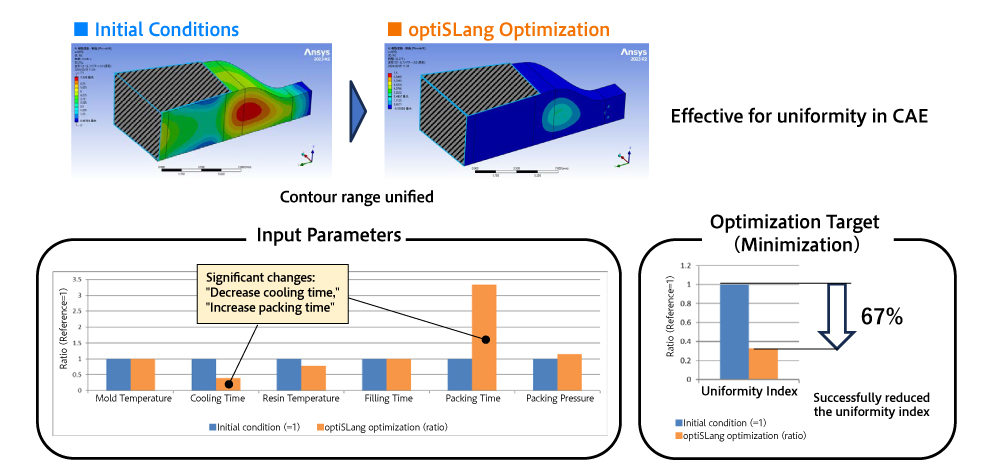
Towards Quality Improvement: Utilization of PlanetsX and optiSLangVisualization of Injection Process Uniformity Using PlanetsX
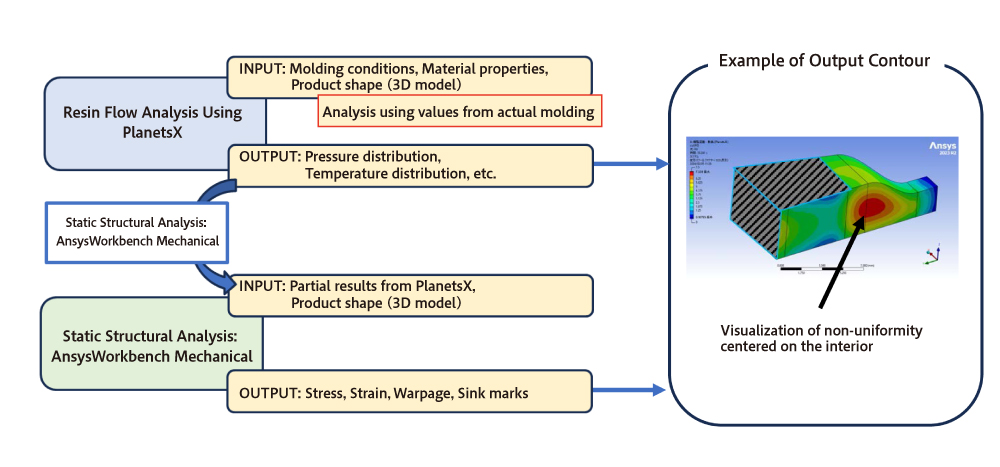
Numerical distribution data serving as indicators of uniformity was obtained.
Finding “optimal conditions” automatically with parameter optimization
Once the cause is identified, the next step is to develop a solution.
This is where parameter optimization is used.
What is parameter optimization?
Manufacturing processes involve fine-tuning of countless variables, or “parameters” such as temperature, pressure, and cycle time. These parameters can be combined in countless ways, making it nearly impossible to find the optimal conditions manually.
Parameter optimization leverages computational power to automatically adjust these conditions, running repeated simulations to identify the combination that yields the best results. It functions like an “expert assistant” that tirelessly runs experiments 24/7.
With conventional CAE, engineers would manually adjust parameters one by one, run a simulation, analyze the results, and repeat. This method was time-consuming and heavily reliant on individual experience and intuition.
To overcome these limitations, a specialized parameter optimization program called optiSLang was used for optimization. By automating the adjustment of multiple variables simultaneously, optiSLang efficiently navigates complex data to pinpoint the optimal processing conditions.
Towards Quality Improvement: Utilization of PlanetsX and optiSLang
What is optiSLang?
・Software that supports parameter optimization for CAE
・Automatically varies multiple parameters to efficiently search for optimal conditions
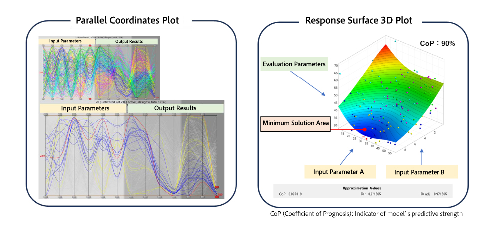
CoP(Coefficient of Prognosis): Indicator of model’s predictive strength
In this case, the optiSLang software was used to run 100 automated simulations. These simulations ran overnight and were completed by the next morning.
With conventional methods, five to 10 conditions could be tested per day. This is a transformative increase in efficiency, turning weeks of work into a single night's processing.
As a result, a 33% reduction in the non-uniformity index compared to the previous baseline was achieved. Specifically,
・Reduced cooling time by 60%
・Increase pressurized time by 230%
Verifying the results through experimentation: Complete elimination of cracks
Positive simulation results are meaningless unless they can be replicated in actual production. Therefore, we conducted actual molding trials using the optimized conditions given in optiSLang.
10 parts were molded. Cracks were successfully eliminated in every single sample. Considering that cracking occurred in every part under the initial conditions, this was a significant improvement.
Towards Quality Improvement: Utilization of PlanetsX and optiSLang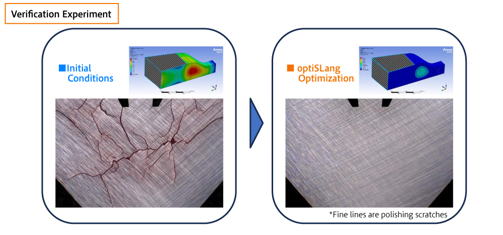
Cracking was eliminated
Improving development processes: A new workflow for engineers
This work did more than solve the cracking problem. It brought significant improvements to the product development process itself.
With parameter optimization software, engineers no longer need to experiment with simulations one by one. Once the objectives, such as “what to optimize,” and “the range of conditions to vary” are set, the optimization proceeds automatically. The results are visualized in an integrated format, presented as easy-to-read graphs and data.
This has significantly reduced the burden on engineers, allowing them to focus on correlations they might have previously missed. Freed from repetitive tasks, engineers can now concentrate on more creative work.
The future of manufacturing with CAE
This article presented just one example of how CAE is transforming manufacturing. To summarize, the key benefits of CAE are
- Making the invisible visible
- Reducing the number of physical prototypes
- Shortening development time
- Enabling improvements in product quality based on scientific evidence
- Reducing development costs
In modern manufacturing, CAE is becoming less of a nice-to-have tool and more of an indispensable technology.
Conclusion
In this article, initiatives to improve the quality of ceramic injection molding using CAE were introduced. By visualizing heterogeneity through fluid analysis and optimizing molding conditions through parameter optimization, a challenge that had persisted for many years, cracking of the part after sintering, was resolved.
At Orbray, we will continue to actively implement advanced simulation technologies to accelerate product development and enhance quality.
We remain committed to driving technological development, utilizing the latest technologies, including CAE, to deliver high-quality products to all of our customers.